
Once the circuit is complete, get the Arduino sketch file from the link at the end of the post. Uploaded the sketch to the Arduino UNO and test the Arduino load cell circuit. Using the Arduino IDE Serial Monitor and using a hacked scale to test the load cell, put some weight on the load cell and note what happens to the analogue reads.
If the analogue readings go up when weight is added to the load cell, then all is fine and move on to the next step. If the analogue readings don’t appear to change or going down instead of up, then the load cell may be installed upside down or the blue/green and white load cell wires need to be swapped round.
INA125 Instrumental Amplifier Circuit Calibration
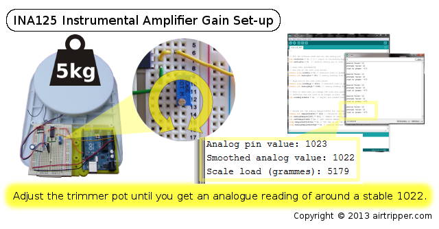
Arduino Load Cell INA125 Instrumental Amplifier Gain Set-up
Rather than mess about with formulas detailed in the INA125 Amplifier data sheet, I went with my own method of calibrating the Arduino load cell circuit. This involve using a trimmer pot to adjust the gain on the INA125 chip to get the voltage range we want for our Arduino analogue pin to read.
Making changes after calibration, like changing wire lengths, altering the circuit and changing the power supply, could upset the gain On the INA125 and cause all other calibrations to be out.
The load cell I’m using is rated for a 5kg load and I want to adjust the gain on the INA125 so that 5v equals 5kg. So basically, I put 5kg on the hacked scale containing the load cell and noted the analogue readings taken from the Arduino load cell circuit using the Arduino IDE Serial Monitor. If the load cell is going to be preloaded with 400 grammes of weight in its intended application, you may want to add this weight to the weight being calibrated. Otherwise you will loose 400 grammes off the target weight range.
The Arduino 10bit A/D converter will give a maximum reading of 1023 and we want to adjust the trimmer pot on the Arduino load cell circuit until 1022/1023 is reached. Ignore the scale load reading at this point as it is yet to be calibrated. Once the gain is set, we can proceed to the next step to calibrate the weight scale of the load cell.
The Filament Force Sensor Firmware
For the Arduino load cell circuit to work it needs firmware in the form of an Arduino IDE sketch. The portion of code below is copied from the sketch which contains variables you need to know to set up the firmware successfully. While the code is well commented, some variables will be covered in more detail in this section and the next section.
// Set the software mode and set the analog pin
int calibrate = 1; // 0 = Output to Processing Application, 1 = Calibration mode
int analogPin = 0; // Arduino analog pin to read
int calibrate = 1; // 0 = Output to Processing Application, 1 = Calibration mode
int analogPin = 0; // Arduino analog pin to read
// LOAD CELL CALIBRATION
// Low end of the test load values
static long loadLow = 0; // measured low end load in grammes from good scales
static int analogLow = 80; // analog reading from load cell for low end test load
// Low end of the test load values
static long loadLow = 0; // measured low end load in grammes from good scales
static int analogLow = 80; // analog reading from load cell for low end test load
// High end of the test load values
static long loadHigh = 5103; // measured high end load in grammes from good scales
static int analogHigh = 1008; // analog reading from load cell for high end test load
static long loadHigh = 5103; // measured high end load in grammes from good scales
static int analogHigh = 1008; // analog reading from load cell for high end test load
// This is used when you change the load cell platform to something else that weighs
// different and the load is no longer on zero. Add an offset to set to zero.
int loadAdjustment = 0; // Adjust non loaded load cell to 0
// different and the load is no longer on zero. Add an offset to set to zero.
int loadAdjustment = 0; // Adjust non loaded load cell to 0
The firmware operates in a mode chosen by the user by setting the calibrate variable to either 0 or 1. Changing modes changes what data is output to the serial interface and what speed the serial interface operates at. Setting the firmware to calibration mode sets the serial baudrate to 9600 and outputs more information to the Arduino IDE serial monitor at 1 second intervals. This mode is ideal for calibrating the Arduino load cell circuit.
Setting calibrate to 0 will set the serial baudrate to 115200 and output just the weight in grammes 100 times a second. Changing the variable plotDelay, not shown in the code snippet, will alter how many times a second data is sent over serial.
The Arduino analogue PIN A0 is used by default and this can be change by assigning a new PIN number to the analogPin variable. Analogue PINs 0 to 5 are available on the Arduino UNO.
Arduino Load Cell Weight Scale Calibration
Calibrating the load cell scale will allow the Arduino code to map grammes to the analogue range that the Arduino load cell circuit can achieve. The calibration, for this application, will achieve a measuring range from zero to 5kg and Zero will be the load cell resting point with no load on the calibration platform. Images are provided as a quick reference to the calibration procedure.
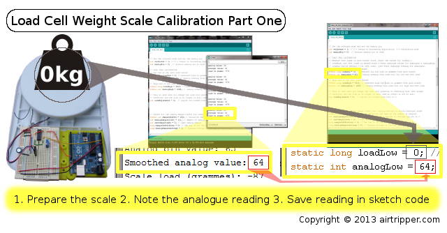
Load Cell Low End Weight Scale Calibration
With the Arduino IDE serial monitor running, note the analogue readings being received from the Arduino load cell circuit. Test the load cell by adding weight to the platform to confirm that the circuit is functioning properly and a good range of readings is possible; you should be getting an analogue range from around 60 to 1022. If the tests look ok then proceed with the calibration, else check the circuit and try the INA125 Instrumental Amplifier gain calibration again.
The first step is to test the low end of the weight scale and you can do this without adding load to the load cell. So the variable loadLow in Arduino sketch code can be assigned 0 as for zero grammes. Then copy the smoothed analogue value to the analogLow variable and move on to the next step.
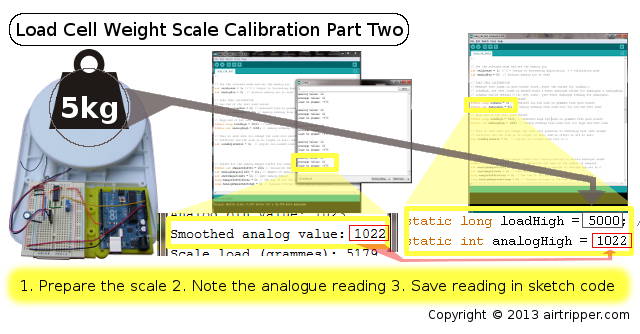
Load Cell High End Weight Scale Calibration
For calibrating the high end of the weight scale some load needs to be put on the load cell scale. The amount of weight to put on the load cell scale should be the amount close to the maximum weight the load cell is rated for. The load being used for calibration should not be so heavy that the analogue readings become stuck at 1023. Adjust the weight so that the analogue readings are a little below 1023.
Measure the weight of a test load as accurately as possible on a good scale, assign the measured weight to the variable loadHigh. Put the test load just weighed on to the load cell platform and copy the analogue reading to the analogHigh variable. Save the Arduino sketch and upload to the Arduino.
The load cell scale should now be calibrated and you can now run weight tests using the Arduino IDE serial monitor for the weight readings.
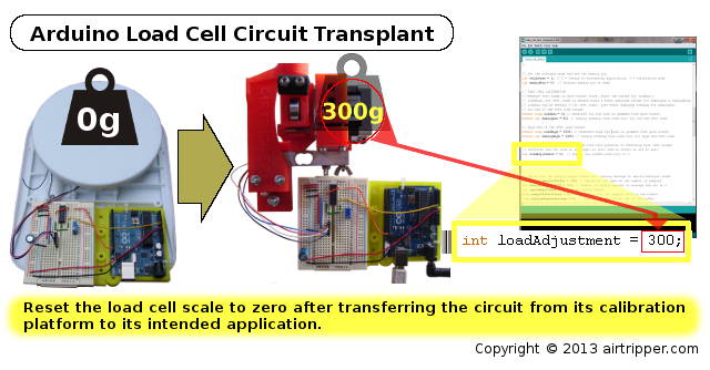
Arduino Load Cell Circuit Transplant
Once the load cell is calibrated it can be transplanted to its intended application. It should be noted that any change in the load cell wire lengths or a change of power supply could effect the gain on the INA125 Instrumental Amplifier and spoil the calibrations.
Setting up the Arduino load cell circuit in another application could change the load cell pre-load weight where zero weight will no longer be set properly. By running the Arduino serial monitor connected to the load cell circuit, you can reset the scale to zero by copying the Scale load (grammes) measure to the variable loadAdjustment.
What Now
The Airtripper Extruder Filament Force Sensor graphing is now done in the Processing Development Environment. This allows me and other users to extend the code and add custom features.
A guide for the Processing Application is being worked on and should be published shortly
The Files
The Arduino load cell Circuit firmware sketch file: https://github.com/Airtripper/load_cell_test


