Why LT motors are delta connected and HT motors are star connected ???

Why LT motors are delta connected and HT motors are star connected?
Ø  Reason is techno commercial.
Ø  In star, phase current is same as line current. But phase voltage is 1/1.732 times line voltage.So insulation required in case of HT motor is less.
Ø  The starting current for motors is 6 to 7 times full load current.So start-up power will be large if HT motors are delta connected.It may cause instability (voltage dip) in case small Power system.
Ø  In starred HT motor starting current will be less compared to delta connected motor. So starting power is reduced. Starting torque will also be reduced. (It will not be a problem as motors are of high capacity).
Ø  Also as current is less copper (Cu) required for winding will be less.
LT motors are delta connected:
Ø  Insulation will not be problem as voltage level is less.
Ø  Starting current will not be problem as starting power in all will be less.
Ø  So no problem of voltage dips.
Ø  Starting torque should be large, as motors are of small capacity.

LT motors have winding delta connected:
Ø  In case it is having star delta starter than they are started as Star connected motor.
Ø  After it attains 80% of synch speed the changeover takes place from star to original configuration delta.
Ø  In star the voltages across the windings are lesser that is 1/1.732 times that available in delta so current is limited.
Ø  When it goes to delta again voltage is full line voltage so current increase even though it is lesser than the line current it remains higher than the line current drawn in star connection at reduced voltage.
Ø  So cables for motor are sized for this current that is what it draws in delta connection.

Working principle of 3Ph. Induction motor...

Working principle of 3Ph. Induction motor...

An electrical motor is such an electromechanical device which converts electrical energy into a mechanical energy. In case of three phase AC operation, most widely used motor is Three phase induction motor as this type of motor does not require any starting device or we can say they are self starting induction motor.For better understanding the principle of three phase induction motor, the basic constructional feature of this motor must be known to us. This Motor consists of two major parts:
Stator:
Stator of three phase induction motor is made up of numbers of slots to construct a 3 phase winding circuit which is connected to 3 phase AC source. The three phase winding are arranged in such a manner in the slots that they produce a rotating magnetic field after 3Ph. AC supply is given to them.
Rotor:
Rotor of three phase induction motor consists of cylindrical laminated core with parallel slots that can carry conductors. Conductors are heavy copper or aluminum bars which fits in each slots & they are short circuited by the end rings. The slots are not exactly made parallel to the axis of the shaft but are slotted a little skewed because this arrangement reduces magnetic humming noise & can avoid stalling of motor.
Working of Three Phase Induction Motor:
The stator of the motor consists of overlapping winding offset by an electrical angle of 120°. When the primary winding or the stator is connected to a 3 phase AC source, it establishes a rotating magnetic field which rotates at the synchronous speed. Secrets Behind the Rotation:
“According to Faraday’s law an emf induced in any circuit is due to the rate of change of magnetic flux linkage through the circuit. As the rotor winding in an induction motor are either closed through an external resistance or directly shorted by end ring, and cut the stator rotating magnetic field, an emf is induced in the rotor copper bar and due to this emf a current flows through the rotor conductor. Here the relative speed between the rotating flux and static rotor conductor is the cause of current generation; hence as per Lenz's law the rotor will rotate in the same direction to reduce the cause i.e. the relative velocity.”
Thus from the working principle of three phase induction motor it may observed that the rotor speed should not reach the synchronous speed produced by the stator. If the speeds equals, there would be no such relative speed, so no emf induced in the rotor, & no current would be flowing, and therefore no torque would be generated. Consequently the rotor can not reach the synchronous speed. The difference between the stator (synchronous speed) and rotor speeds is called the slip. The rotation of the magnetic field in an induction motor has the advantage that no electrical connections need to be made to the rotor.
Thus the three phase induction motor is:
Ø  Self-starting.
Ø  Less armature reaction and brush sparking because of the absence of commutators and brushes that may cause sparks.
Ø  Robust in construction.
Ø  Economical.
Ø  Easier to maintain.

Induction motor is a generalized transformer...

Introduction:
What is the fundamental difference in working principle of induction motor and transformer?That is even though the equivalent circuit of motor and transformer is same rotor of motor rotates whereas secondary of transformer do not.
Alternating flux machine and Rotating flux machine:
Induction motor is a generalized transformer. Difference is that transformer is an alternating flux machine while induction motor is rotating flux machine. Rotating flux is only possible when 3 phase voltage (or poly phase) which is 120 degree apart in time is applied to a three phase winding (or poly phase winding) 120 degree apart in space then a three phase rotating magnetic flux is produced whose magnitude is constant but direction keeps changing. In transformer the flux produced is time alternating and not rotating.
Air gap and Reluctance:
There is no air gap between primary and secondary of transformer where as there is a distinct air gap between stator and rotor of motor which gives mechanical movability to motor. Because of higher reluctance ( or low permeability) of air gap the magnetizing current required in motor is 25-40% of rated current of motor where as in transformer it is only 2 -5 % of rated primary current.
Frequency:
In an alternating flux machine frequency of induced EMF in primary and secondary side is same where as frequency of rotor EMF depends on slip. During starting when S = 1 the frequency of induced EMF in rotor and stator is same but after loading it is not.
Other difference is that the secondary winding and core is mounted on a shaft set in bearings free to rotate and hence the name rotor. If at all secondary of a transformer is mounted on shaft set at bearings the rate of cutting of mutual magnetic flux with secondary circuit would be different from primary and their frequency would be different. The induced EMF would not be in proportion to number of turns ratio but product of turn ratio and frequency. The ratio of primary frequency to the secondary frequency is called slip.
Any current carrying conductor if placed in magnetic field experience a force so rotor conductor experience a torque and as per Lenz’s Law the direction of motion is such that it tries to oppose the change which has caused so it starts chasing the field.

Power flow diagram of induction motor:


Stator input electrical power = A
Stator losses = B
Rotor losses = C
Mechanical output = P
A – ( B + C ) = P
Roughly B= 0.03A, C= 0.04A
A – 0.07A = P
0.93A = P, Hence efficiency = (P/A) x 100 = 93%

Why is My 12 Volt Battery Reading as 13 Volts?

Why is My 12 Volt Battery Reading as 13 Volts?

Why is My 12 Volt Battery Reading as 13 Volts?

Inside diagram of Lead acid battery
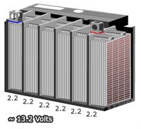
All Lead acid batteries (Gel, AGM, Flooded, Drycell, etc) are made up of a series of 2.2 volt cells that are bridged together in series to reach their final desired voltage. For instance, a 6 volt battery will have 3 cells (3 x2.2= 6.6 volts), a 12 volt battery will have 6 cells (6 x2.2=13.2 volts) and so on.That 2.2 volts is the fully charged, straight off the charger number. The actual resting voltage, or the voltage a battery will settle at 12-24 hours after being removed from the charger, is closer to 2.1 volts per cell, or about 6.4 volts for a 6v battery, and 12.7 volts for a 12v battery. These numbers assume 100% healthy cells, and may vary a bit lower for older batteries.

Source: https://www.batterystuff.com

What is Transimpesdence Amplifier ???

What is Transimpesdence Amplifier ???
    One of the first things you learn about operational amplifiers (op amps) is that the op amp's gain is very high. Now, let's connect a feedback resistor across it, from the output to the -input. When you put some input current into the -input (also known as the summing point), the gain is so high that all of the current must go through the feedback resistor. So, the output will be VOUT = -(IIN × RF). While we used to call this a "current-to-voltage converter," which it is indeed, it's also sometimes referred to as a "transimpedance amplifier," where the "gain" or "transimpedance" is equal to RF.

Quick note to Choose the right frame size of motors...

Quick note  to Choose the right frame size of motors...
       To confidence you are ordering the right motor for your specific application, you must understand motor frame designations. Miniaturization isn't just for electronics. And you probably know carmakers pack more ponies into smaller engines these days. The same thing has taken place with industrial motors. Compared to their predecessors, today's motors pack more horsepower into a smaller physical
To have confidence you are ordering the right motor for your specific application, you must understand motor frame designations.
Miniaturization isn't just for electronics. And you probably know carmakers pack more ponies into smaller engines these days. The same thing has taken place with industrial motors. Compared to their predecessors, today's motors pack more horsepower into a smaller physical size. Fortunately, the National Electric Manufacturers Association (NEMA) provides us with frame size standardization, so you can make intelligent choices among the different sizes of motors.
This frame size standardization is a key part of motor interchangeability. This means the same horsepower, speed, and enclosure will normally have the same frame size from different motor manufacturers. Thus, you can replace a motor from one manufacturer with a similar motor from another, if they are both in standard frame sizes.
Thanks to standardization, we have three groups of frame sizes. The oldest is original. In 1952, manufacturers made new frame assignments: U frames. They introduced T frames in 1964.
Original frame size motors (pre-1952) still in existence will need replacement in the near future. And, yes, such motors still operate today. For example, the Panama Canal still uses two motors that have operated as long as the canal itself.
Also, the many U frame motors that followed original motors will eventually fail and require replacement. Thus, you need strong reference material on frame sizes, and some knowledge of changes that took place as a part of the so-called rerate programs.
Motors with the same three frame-size digits have the same base mounting hole spacing and shaft height.
Rerating and temperatures. Why can we rerate motor frames to get more horsepower in a frame? For the most part,this is the result of improvements made in motor design and insulating materials. Newer insulations allow a motor to run much hotter; and thus handle the extra heat generated when producing more horsepower.
The original NEMA frame sizes ran at very low temperatures, but the U frame motors have Class A insulation with a rating of 105DegrC. T frame motor designs run even hotter. Their Class B insulation has a temperature rating of 130DegrC. This increase in temperature capability made a corresponding increase in horsepower in the same size package possible.
To accommodate the larger mechanical horsepower capability, shaft and bearing sizes had to increase. Thus, the original 254 frame (5 hp at 1800 rpm) has a one and one-eighth-in. shaft. The 254U frame (7.5 hp at 1800 rpm) has a one and 3-eighths-in. shaft, and the 254T frame (15 hp at 1800 rpm) has a one and fivbe-eighths-in. shaft. Bearing diameters also increased to accommodate the larger shaft sizes and heavier loads associated with the higher horsepower.
Frame size basis. At first glance, the frame size numbering system may seem capricious, but there is some logic to it. For example, the first two digits of a three-digit frame size relate to the shaft height of a foot-mounted (rigid base) motor in quarters of an inch. You can use this value to figure shaft height (D dimension). Just divide the first two digits by four. Thus, a 405 frame (original, U frame, or T frame) has a shaft height of 40 divided by 4, or 10 in.
Although no direct inch measurement relates to it, the third digit of three-digit frame sizes is an indication of the motor body's length. The longer the motor body, the longer the distance between mounting bolt holes in the base (greater F dimension). For example, a 145T frame has a larger F dimension than does a 143T frame.
The term "fractional horsepower" covers those frame sizes having two-digit designations, as opposed to three-digit designations. The frame sizes normally associated with fractional horsepower motors are 42, 48, and 56. In this case, each frame size designates a particular shaft height, shaft diameter, and face or base mounting hole pattern.
In these motors, specific frame assignments do not relate to horsepower and speed. So, it's possible a particular horsepower and speed combination might exist in three different frame sizes. In this case, it's essential you know the frame size as well as the horsepower, speed, and enclosure type.
The two-digit frame number relates to the shaft height in sixteenths of an inch. You can figure that a 48-frame motor will have a shaft height of 48 divided by 16, or 3 in. Similarly, a 56-frame motor has a shaft height of 3.5 in.
From the 56 frame on up, motors are available in horsepowers greater than those normally associated with fractionals. For example, 56 frame motors go as high as 5 hp. For this reason, calling motors with two-digit frame sizes "fractionals" is somewhat misleading.
Selecting the right motor is a complicated process. But, if you know the frame size, you'll simplify the process significantly.
This text is an adaptation of The Cowern Papers, courtesy Baldor Electric Co., Wallingford, Conn., edited by Mark Lamendola, EC&M Technical Editor. Cowern is an Application Engineer for Baldor.
Source : www.ecmweb.com

Detailed explanation of Battery Charging with Modes ....

Detailed explanation of Battery Charging  with Modes ....
            Mobile devices are becoming an integrated part of our daily life. Let’s use the smartphone as an example. Instead of a simple phone call function, smartphones are now packed with rich features for social networking, web browsing, messaging, gaming, large HD screens and many others. All these features are pushing the phone to become a power-hungry device. Battery capacity and energy density have been increased substantially to meet the higher power requirements. A 10-minute charge that supports a device for one day or charging one hour to achieve an 80 percent state-of-charge is becoming a trend for high-end user experiences. When combining rapid charge requirements with a large battery capacity, the charge current in a portable device could reach up to 4 A or higher. This demand for high power brings a lot of new challenges to a battery-powered system design.
USB Power
A 5 V USB power source is commonly used in portable devices. A traditional USB port has a maximum output current of 500 mA for USB 2.0, or 900 mA for USB3.0, which is insufficient to rapidly charge a portable device. A USB adapter (dedicated charge port, or DCP) can increase the output current up to 1.8 A with a micro-USB connector. Unfortunately, a typical 5 V/2 A power adapter only provides a total of 10 W power capability. Using such a power adapter as a power source for the charger, the battery charger only provides up to 2.5 A charge current. This is not high enough to fast-charge a battery pack of 4,000 mAh and above. Can we continue to increase the output current of a 5 V power adapter in order to increase power? In theory, yes, if we increase the cost and use a special cable. However, there are some limitations:
•  A higher adapter current (for example, 2 A or higher) requires a thicker cable wire and special USB connector, which increases the system solution cost. Additionally, the traditional USB cable is not good enough due to power loss and safety concerns.
• The typical impedance of an adapter cable wire is from around 150 to 300 mOhm, depending on the cable’s length and thickness. High adapter output current causes a higher voltage drop across the cable wire and reduces the effective input voltage of the charger input. When the charger input voltage is close to battery charge voltage, the charge current significantly decreases, which increases charge time.
Using a 5 V/3 A adapter with 180 mOhm cable resistance, for example, the voltage drop across the cable is 540 mV. Now the charger’s input voltage is 4.46 V. Let’s assume that the total resistance from the charger input to the battery pack is 150 mOhm. This includes the power MOSFET’s on-resistance from the charger and inductor DC resistance. The maximum charge current is only 730 mA for charging a 4.35 V lithium-ion (Li-Ion) battery cell, even if the charger is capable of supporting 3 A. Less than 1 A charge current is definitely not high enough to achieve a fast charge.
Based on the above analysis, the power source input voltage must increase to provide enough voltage in order to keep the charger from entering dropout mode. Due to these limitations, when a system requires higher than 10 W or 15 W power, a high-voltage adapter is preferred, such as 9 V or 12 V. A high-voltage adapter requires less input current for the same power and has more input voltage margin to fully charge the battery voltage. The only limitation with a high-voltage adapter is a backwards compatibility issue. If a high-voltage adapter is plugged into a portable device designed to support 5 V input, either a system shut-down (due to overvoltage protection), or possibly damage the device (due to insufficient high-voltage protection) could occur.
Because of these limitations, many new hybrid high-voltage adapters such as the USB Power Delivery adapter are coming to market. A common feature of these hybrid voltage adapters is the capability to recognize system voltage requirements with a handshake between the adapter and system controller. The adapter starts with 5 V output as a default value. It only raises the voltage to a higher value of 9 V or 12 V when the system confirms it can support it to achieve fast charging. The system and adapter communication can be accomplished through either VBUS or D+ and D- lines using a special handshaking algorithm or signal. This new hybrid adjustable voltage adapter can become a universal power source to support both a traditional 5 V as a popular power source, and a high input voltage system for fast charging.
Fast Battery Charging
Can we further reduce the charge time through some unique battery charging approach without increasing input power or charge current? To find out, let’s take a look at the battery-charging cycle.
There are two operation modes in a battery charging cycle: constant current (CC) and constant voltage (CV) modes. A charger operates at CC mode when the battery voltage is below the regulated charge voltage. Once the sensed battery pack terminal voltage reaches a predetermined regulation voltage, it enters CV mode. Battery charging is terminated when the real battery current reaches termination current. This is usually about five to 10 percent of the full fast charge current.
In an ideal charging system, without any resistance in the battery pack, only constant current mode exists. It has the shortest charge time without CV charging mode. This is because the charge current immediately drops to zero and reaches the charge termination current once the charge voltage reaches the regulated charge voltage.
However, in a real battery-charging system, there is a series of resistances from the battery voltage-sensing point to the battery cell. Such resistance includes: 1) the PCB trace; 2) the on-resistance of two battery charging and discharging protection MOSFETs; 3) current sense resistance to measure the battery charge and discharge current for over-current protection in the fuel gauge; and 4) battery cell internal resistance, which is a function of battery cell aging, temperature, and state-of-charge.
With a 1C charge rate for a new battery cell, the charger takes about 30 percent charging time in CC mode to reach about 70 percent of the battery capacity. Conversely, it takes about 70 percent of the total charge time to achieve only 30 percent of the battery capacity in CV mode. The higher the battery pack’s internal resistance, the longer the charge time is required in CV mode. Only when the battery open circuit voltage reaches the maximum charge voltage is the battery then fully charged. With a higher resistance between the battery charge voltage sensing point and real battery cell, even when the battery pack sensing voltage reaches the regulated voltage, the real battery cell open circuit voltage is still lower than the desired regulated voltage.
Things become more challenging with a higher charge current like 4 A or higher in smartphone and tablet applications. At such a high-charge current, the voltage drop on PCB trace, or the battery pack’s internal resistance, increases significantly. This causes the charger to enter CV mode earlier, which slows down the charging. How do we reduce the charge time due to this high voltage drop?
By closely monitoring the charge current, the voltage drop in the charge path can be estimated accurately in real time. The resistance compensation technique called IR compensation raises the battery regulation voltage to compensate for the additional voltage drop in the charging path. Now the charger stays in constant-current regulation mode longer until the real battery cell open circuit voltage is very close to the desired voltage value. In this way, CV charging-mode time can be reduced significantly, reducing total charge time by as much as 20 percent.
System Thermal Optimization
To achieve a fast-charging function, use a higher power adapter like 9 V/1.8 A and 12 V/2 A. In addition to charging the battery, a battery charger also powers the system. It is one of the hottest spots in the portable power device. For a better end user experience, the maximum temperature rise between the device case and ambient temperature should not exceed 15°C. This is why the battery charger power conversion efficiency and system thermal performance become more critical. How do we achieve best thermal performance and efficiency?
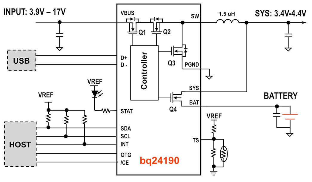
Figure 1. This block diagram represents a 4.5 A I2C high-efficiency switching charger.
Figure 1 shows the simplified application circuit diagram of a 4.5 A high-efficiency switch-mode charger. This charger supports both a USB and AC adapter, and all the MOSFETs are integrated. MOSFETs Q2 and Q3 and inductor L are composed of a synchronous switching buck-based battery charger. This combination achieves the highest possible battery charging efficiency and fully uses the adapter power for achieving fastest charging. MOSFET Q1 is used as a battery reverse blocking MOSFET to prevent battery leakage to the input through the body diode of MOSFET Q2. It is also used as an input current-sensing element to monitor the adapter current. MOSFET Q4 is used to actively monitor and control the battery-charging current. All the FETs have to be designed with sufficiently low on-resistance to achieve high efficiency. To further improve thermal performance, a thermal regulation loop is introduced. It maintains the maximum junction temperature by reducing the charge current once it reaches the pre-defined junction temperature.
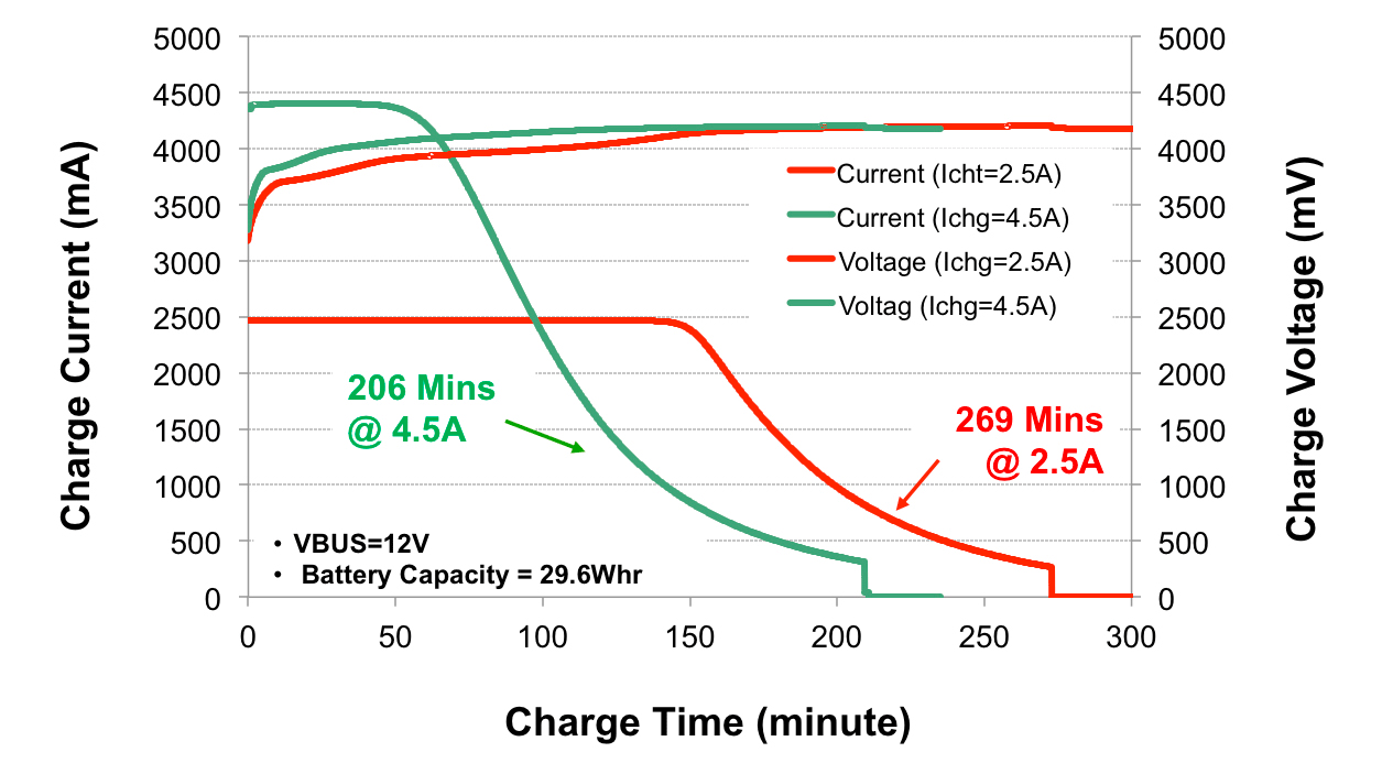
FIGURE_02_LI-&-QIAN
Figure 2. Charge time comparison with different charge current: 2.5 A vs 4.5 A.
Experimental Test Results
Figure 2 shows the relationship between the charge current to the charge time. It is easy to understand that a high-charge current achieves faster charge, as long as the battery charge current rate doesn’t exceed the maximum rate specified by the battery cell manufacturer. As shown in Figure 2, charge time is reduced by 30 percent. In other words, charging minutes are reduced from 269 to 206 when the charge current increases from 2.5 A to 4.5 A.
Figure 3 shows the charging time benefit using an IR compensation technique in a practical charger design. Charge time is reduced by 17 percent, or from 234 to 200
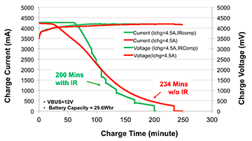
Figure 3. Fast charge comparison with IR compensation, driving charge time down from 234 to 200 minutes.
minutes with 4.5 A charge current. This is accomplished by compensating 70 mOhm resistance for charging a single-cell 8,000 mAh battery without additional cost increase and thermal impact.
Summary
Rapid charge is becoming ever more important in many portable devices. This requires new design considerations in the practical charging system, including a new type of high-voltage adapters, charge current and thermal optimization. Also required is an advanced charging profile to optimize charge time and improve battery life. The experimental results provided demonstrate the effectiveness of the design for rapid charge.
References
For more information about battery charge management, visit:
www.ti.com/batterycharger-ca.
Download a datasheet for the bq24190 here:www.ti.com/bq24190-ca.
Michelle Qiong Li is a systems and applications engineering manager and leads the engineering team in TI’s Battery Charger Management group. She holds 14 U.S. patents.
Jinrong Qian is a product line manager of battery charge management and an Emeritus Distinguished Member of the TI’s Technical Staff for Battery Management Solutions. He has published a myriad of peer-reviewed power electronics transactions and power management papers, and holds 28 U.S. patents.
If you have any questions about this article, please contact ti_jinrongqian@list.ti.com.
Source : Batterypoweronline.com

Difference between unearthed cables and earthed cables and their relationship with Insulatuon level

Difference between unearthed cables and earthed cables and their relationship with Insulatuon level

Introduction:

  • In HT electrical distribution, the system can be earthed or unearthed. The selection of earthed/unearthed cable will depend on system. If distribution system is earthed then we have to use cable which is manufactured for earthed system. (Which the manufacturer specifies). If the system is unearthed then we need to use cable which is manufactured for unearthed system. The unearthed system requires high insulation level compared to earthed System.
  • For earthed and unearthed XLPE cables, the IS 7098 part2 1985 does not give any difference in specification. The insulation level for cable for unearthed system has to be more.

Earthed System:         

  • Earlier the generators and transformers were of small capacities and hence the fault current was less. The star point was solidly grounded. This is called earthed system.
  • In Three phases earthed system, phase to earth voltage is 1.732 times less than phase to phase voltage. Therefore voltage stress on cable to armor is 1.732 times less than voltage stress between conductors to conductor.
  • Where in unearthed system, (if system neutral is not grounded) phase to ground voltage can be equal to phase to phase voltage. In such case the insulation level of conductor to armor should be equal to insulation level of conductor to conductor.
  • In an earthed cable, the three phase of cable are earthed to a ground. Each of the phases of system is grounded to earth. Examples: 1.9/3.3 KV, 3.8/6.6 KV system

 Unearthed System:

  • Today generators of 500MVA capacities are used and therefore the fault level has increased. In case of an earth fault, heavy current flows into the fault and this lead to damage of generators and transformers. To reduce the fault current, the star point is connected to earth through a resistance. If an earth fault occurs on one phase, the voltage of the faulty phase with respect to earth appears across the resistance. Therefore, the voltage of the other two healthy phases with respect to earth rises by 1.7 times. If the insulation of these phases is not designed for these increased voltages, they may develop earth fault. This is called unearthed system.
  • In an unearth system, the phases are not grounded to earth .As a result of which there are chances of getting shock by personnel who are operating it.Examples : 6.6/6.6 KV, 3.3/3.3 KV system.
  • Unearthed cable has more insulation strength as compared to earthed cable. When fault occur phase to ground voltage is √3 time the normal phase to ground voltage. So if we used earthed cable in unearthed System, It may be chances of insulation puncture. So unearthed cable are used. Such type of cable is used in 6.6 KV systems where resistance type earthing is used.

 Nomenclature:

  • In simple logic the 11 KV earthed cable is suitable for use in 6.6 KV unearthed system. The process of manufacture of cable is same. The size of cable will depend on current rating and voltage level.
  • Voltage Grade (Uo/U) where Uo is Phase to Earth Voltage & U is Phase to Phase Voltage.
  • Earthed system has insulation grade of KV / 1.75 x KV.
  • For Earthed System (Uo/U): 1.9/3.3 kV, 3.8/6.6 kV, 6.35/11 kV, 12.7/22 kV and 19/33 kV.
  • Unearthed system has insulation grade of KV / KV.
  • For Unearthed System (Uo/U): 3.3/3.3 kV and 11/11 kV.
  • 3 phase 3 wire system has normally Unearthed grade cables and 3 phase 4 wire systems can be used earthed grade cables, insulation used is less, and cost is less.

Thumb Rule:

  • As a thumb rule we can say that 6.6KV unearthed cable is equal to 11k earthed cable i.e6.6/6.6kvUnearthed cable can be used for 6.6/11kv earthed system. because each core of cable have the insulation level to withstand 6.6kv so between core to core insulation level will be 6.6kv+6.6kv = 11kv
  • For transmission of HT, earthed cable will be more economical due to low cost where as unearthed cables are not economical but insulation will be good.
  • Generally 6.6 kV and 11kV systems are earthed through a neutral grounding resistor and the shield and armor are also earthed, especially in industrial power distribution applications.  Such a case is similar to an unearthed application but with earthed shield (some times called solid bonding).  In such cases, unearthed cables may be used so that the core insulation will have enough strength but current rating is de-rated to the value of earthed cables. But it is always better to mention the type of system earthing in the cable specification when ordering the cables so that the cable manufacturer will take care of insulation strength and de rating.
Source: Electricalnotes.wordpress.com

What is XLPE and PVC Insulations in Conductors ?

What is XLPE and PVC Insulations in Conductors ?
PVC is Polyvinyl Chloride and XLPE is cross linked Poly ethylene which is more chemically stable

XLPE cable can be used for Low, medium and high voltage applications. Conductor is insulated with XLPE which can withstand higher conductor temperature during normal and short circuit condition. It has better insulation value, lighter in weight and better current capacity with lesser  bending radius.Depending on application, it is selected and in areas which Is having moisture XLPE cables are preferred. It has lesser chance of mechanical damage and can be used for underground application with armouring and MDPE outersheathing.